单片机开发 | MCU Development
A microcontroller (MCU for microcontroller unit) is a compact integrated circuit designed to govern a specific operation in an embedded system. Typically, microcontrollers include an application-specific processor, memory, and input/output peripherals on a single chip.
By offering a customizable mix of read/write memory, program memory, and processing capability, microcontrollers make it economical to digitally control even more devices and processes.
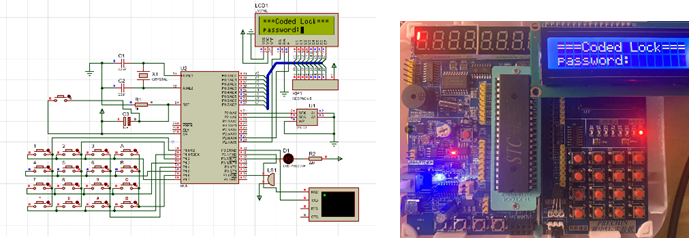
Figure 1 depicts the circuit diagram we constructed within the simulation software to verify the rationality of the design.

The control of a system is inextricably linked to the collaborative operation of hardware electronic circuits and the computational processing of chips. In this course, we have delved into the underlying operational principles of computer systems and their hardware realizations, acquiring proficiency in assembly language, principles of compilation, and system hardware simulation.
Owing to the difficulty in modifying circuit PCB boards post-production, it is imperative to simulate the system circuitry prior to the actual soldering of hardware circuits and chips, to validate the feasibility of the code and design proposals.
As illustrated in Figure 2, the electronic password lock controlled by the C51 chip is presented, where we have learned how to employ matrix keyboards, utilize buzzers for music playback, and implement Bluetooth serial communication for data transfer among other hardware control and programming techniques.
FPGA Development

FPGAs (Field-Programmable Gate Arrays) are renowned for their abundant hardware resources, precise timing, and obviation of traditional gate circuits, offering high convenience and accuracy in development. They are extensively utilized in sectors such as communications, industry, and aerospace. Leveraging these attributes, learning FPGA enables the execution of highly precise timing and logic controls with minimal need for hardware expansion. This course has facilitated the mastery of EDA (Electronic Design Automation) frameworks and the Verilog hardware description language. Figure 3 presents a digital signal generator based on Verilog and FPGA, capable of generating various voltage signals with high precision.

After the programming component was validated through simulation, the hardware circuit was constructed. Utilizing peripheral hardware circuits, we have implemented the functionality to switch between different waveforms, as well as adjust their amplitude and frequency. The right image displays the waveform output as captured by an oscilloscope.